Page 1 of 1
Looking for pin-outs for 2014 RTW alarm system
Posted: Wed Mar 25, 2020 7:43 pm
by gadgetgaz
The alarm unit has two connectors, one is an 11-way block and looks to be fully populated, the other is 8-way with 4 wires connected.
Does anyone have or can point me towards the pin-outs please?
Thanks.
Re: Looking for pin-outs for 2014 RTW alarm system
Posted: Wed Mar 25, 2020 9:48 pm
by David.
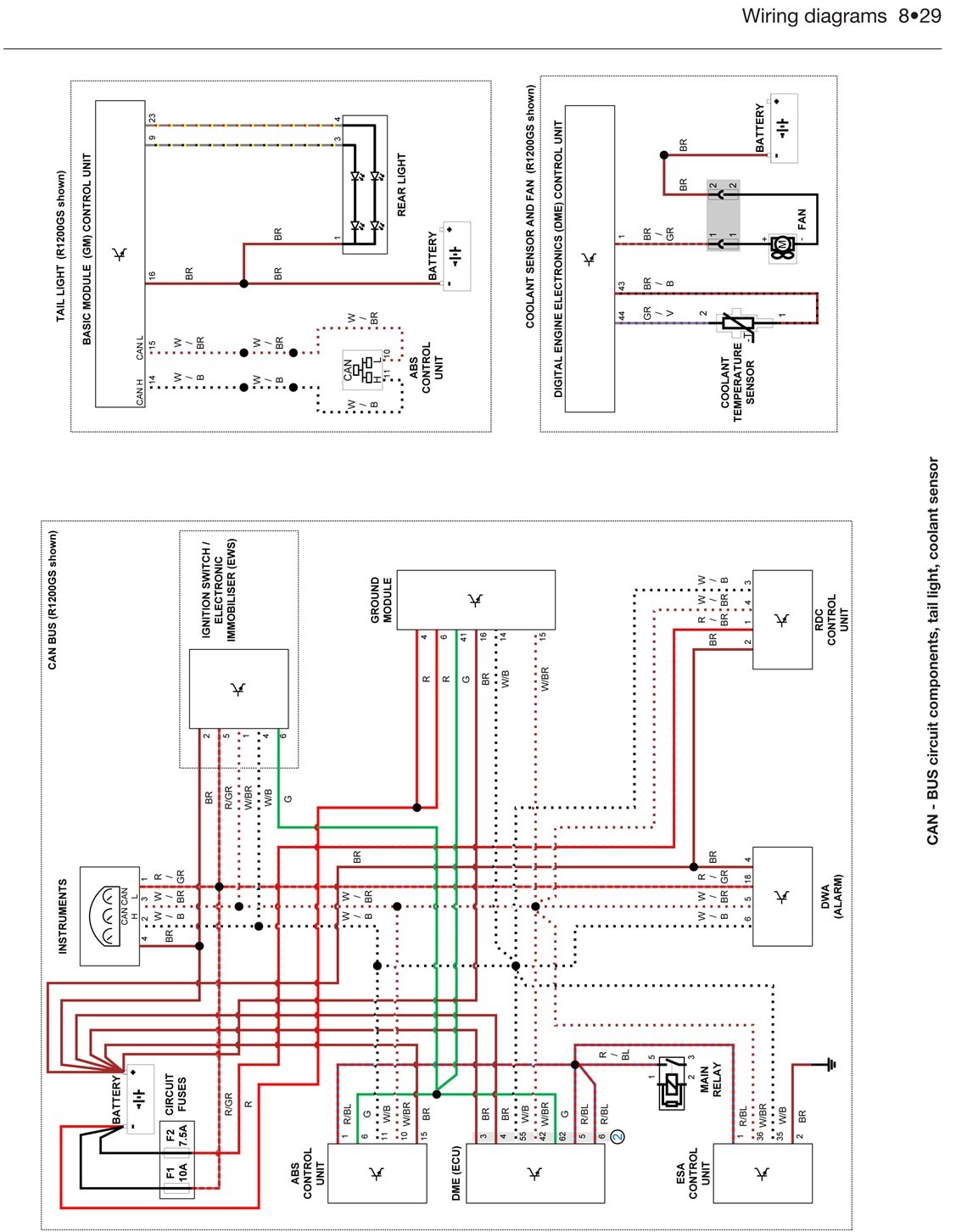
Is this any help, it says GS but is from the same Haynes manual for RT's, (click on to enlarge).

Re: Looking for pin-outs for 2014 RTW alarm system
Posted: Wed Mar 25, 2020 11:07 pm
by gadgetgaz
It doesn't seem to be the same module. The DWA on the diagram only has 4 wires going to it whereas the module on my bike has 5 in one connector and about ten in another. Goodness knows why there are so many, I wonder if the immobiliser is combined into the same unit?
Thanks a lot for your efforts though, David.
Re: Looking for pin-outs for 2014 RTW alarm system
Posted: Thu Mar 26, 2020 10:07 am
by David.
Has the bike got RDC (Tyre pressure monitoring), if so, it may be a combined unit for both DWA (Alarm) & RDC.
Some bikes do have a separate RDC unit like this one.

If you don't have either DWA or RDC, you'll have 3 connectors like these lying around under the seat.

Not sure if this is any help, may I ask the reason for the original question.
gadgetgaz wrote:Does anyone have or can point me towards the pin-outs please?
Re: Looking for pin-outs for 2014 RTW alarm system
Posted: Thu Mar 26, 2020 11:02 am
by gadgetgaz
All those sockets have something plugged in on my bike.
This picture shows the RDC module you mentioned (I think) far left.
The two plugs I mentioned are visible at the back of the alarm module. The plug on the right might be the one in the diagram you posted.

My reason for asking relates to
my post in the gps section. I want the alarm to go off if someone tampers with the GPS release button even if it is locked with a central locking mod. I'm looking to tap into the tilt sensor maybe or, at least to temporarily interrupt the power supply to the alarm module thus triggering an alarm.
Re: Looking for pin-outs for 2014 RTW alarm system
Posted: Fri Mar 27, 2020 8:47 am
by David.

Looking at the top RHS connector, it has 5 wires. Comparing this to a wiring diagram in a Haynes manual for the Anti-theft system on a Camhead it looks very similar.
Green/White = To instruments
Red = To battery positive
Brown = To battery negative
The other 2 wires look like White/Brown and White/Black, the manual says,
"Note - where anti-theft/tyre pressure control unit is not fitted, the CAN bus is terminated with a terminating resistor."
Normally, Red = +ve and Brown = -ve.
If you are brave enough, a voltage check between the Red wire and a good earth or directly to the battery's negative terminal may prove the above theory.
Re: Looking for pin-outs for 2014 RTW alarm system
Posted: Fri Mar 27, 2020 11:08 am
by gadgetgaz
Thanks again David. I tested the wires and, as you say the brown is ground and the red is +ve. That red has actually got a different coloured stripe but I can't remember what colour. I cut the wire to check it activated the alarm and yes it does. The alarm has a battery isolation alarm function so it goes off using its own internal battery and soon as the power is reapplied the alarm continues until reset. When you deactivate the alarm it gives you an indication of what caused the alarm by the number of LED flashes. I can't find any other way of electrically activating the alarm such as an accessory loop so I will be using this method to make the GPS release button press in a micro switch that will cut the power to the alarm momentarily. It would also work with an accessory loop
It seems to work ok.
Re: Looking for pin-outs for 2014 RTW alarm system
Posted: Fri Mar 27, 2020 12:34 pm
by David.
Sounds like a result, thank you for the feedback.
Re: Looking for pin-outs for 2014 RTW alarm system
Posted: Fri Mar 27, 2020 12:48 pm
by gadgetgaz
Thanks I'll update
my post in the GPS section with my progress on making the alarm activate when the GPS release button is pressed whilst the alarm is set.


